Electrical characteristics of spark generators for automotive ignition Page: 22 of 30
This report is part of the collection entitled: National Advisory Committee for Aeronautics Collection and was provided to UNT Digital Library by the UNT Libraries Government Documents Department.
Extracted Text
The following text was automatically extracted from the image on this page using optical character recognition software:
REPORT NATIONAL ADVISORY COMMITTEE FOR AERONAUTICS
which the system actually has delivered into its capacitance at the instant of maximum voltage.
Column 4, on the other hand, gives the energy which was apparently available at the instant
of break, as indicated by the current determined by the oscillograph and the inductance deter-
mined by the flux meter. A comparison of columns 4 and 6 shows a very low efficiency as indi-
cated by the figures in column 7, which are the quotients obtained by dividing the numbers in
column 6 by those in column 4. These show that in one case less than one-tenth and in all but
one case less than four-tenths of the energy originally at hand appears in ths secondary at the
time when it is most wanted to raise the voltage at the plug electrodes. If, however, the spark
gap is so short that a spark can easily be produced, we find that the energy then delivered into
it has the values 2 shown by the figures in column 5. Strangely enough these values are much
greater than those in column 6 and thus show that there must be some process occurring while
the voltage is building up which ties up much of the original energy in unavailable form, but
which will release at least part of it later to be dissipated as heat in the spark gap. While rota-
tional energy may account for some of the excess of column 5 over column 6 in the case of
the magnetos, it can not do so in the battery
uoo systems, and it can not accout n for the great
difference between column 4 and column 6
o _- - - _ since it was not included in the computation
of either energy value. An estimate of the
possible energy losses in the resistance of the
o - - windings during the time the voltage is build-
ing up shows them to be negligible, and we
must therefore attribute the low efficiency to
40 - some other cause. Eddy currents induced in
the core, pole faces, and other parts of the
20 magnetic circuit seem to be the principal
cause of this poor performance.
X. An independent arid roughly quantitative
01 1 C K estimate of the effects to be expected from
A P C D E F H /J K
eddycurrents can be obtained from alternating-
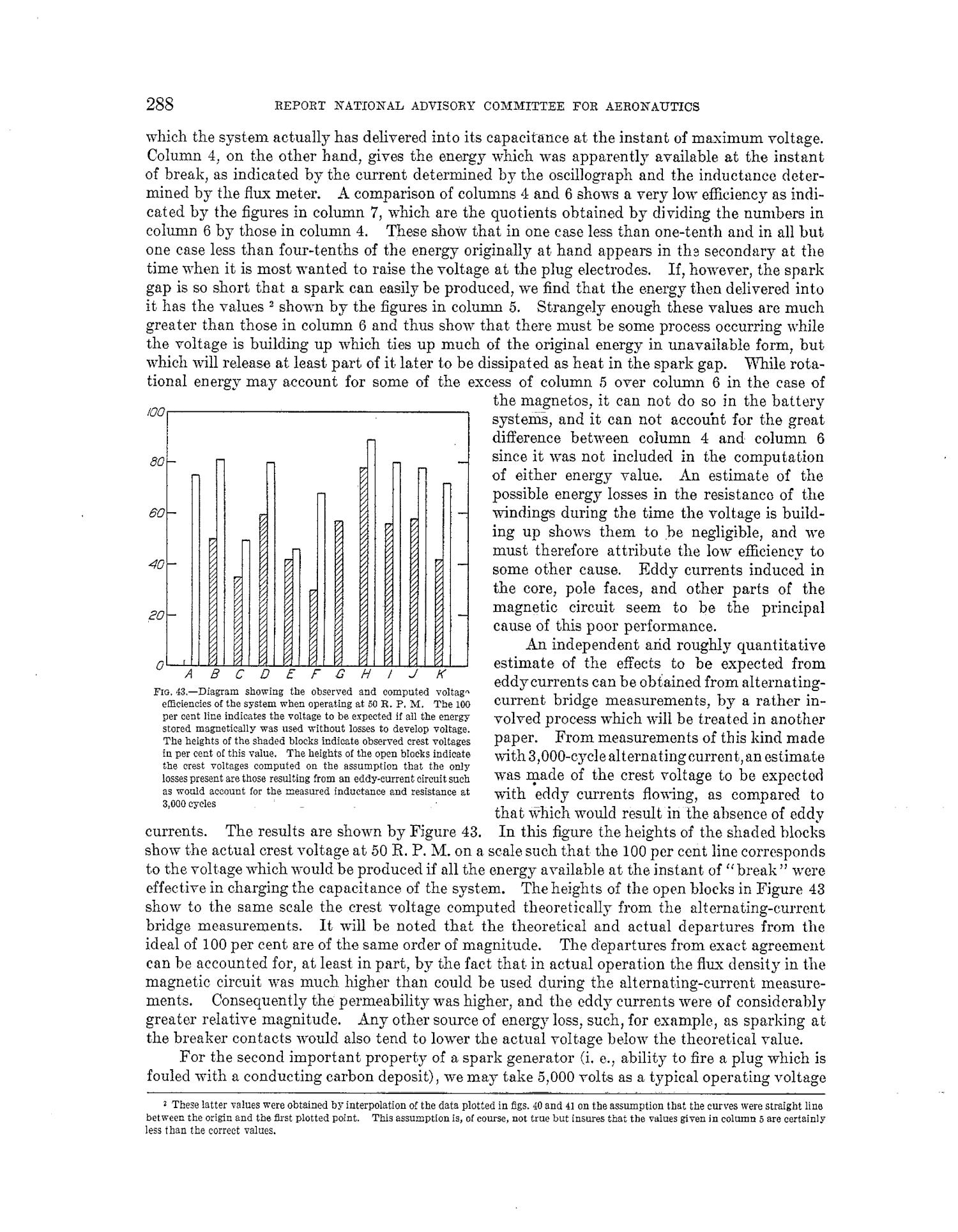
Flo, 43.-Diagram showing the observed and computed voltag eddycurrents can be obtained from alternating-
eMiciencies of the system when operating at 50 R. P. M. The 100 current bridge measurements, by a rather in-
per cent line indicates the voltage to be expected if all the energy volved process which will be treated in another
stored magnetically was used without losses to develop voltage.
The heights of the shaded blocks indicate observed crest voltages paper. From measurements of this kind made
in per cent of this value. The heights of the open blocks indicate with 3,000-cycle alternating current,an estimate
the crest voltages computed on the assumption that the only
losses present are those resulting from an eddy-current circuit such waS made of the crest voltage to be expected
as would account for the measured inductance and resistance at with eddy currents flowing, as compared to
3,000 cycles that which would result in the absence of eddy
currents. The results are shown by Figure 43. In this figure the heights of the shaded blocks
show the actual crest voltage at 50 R. P. M. on a scale such that the 100 per cent line corresponds
to the voltage which would be produced if all the energy available at the instant of "break" were
effective in charging the capacitance of the system. The heights of the open blocks in Figure 43
show to the same scale the crest voltage computed theoretically from the alternating-current
bridge measurements. It will be noted that the theoretical and actual departures from the
ideal of 100 per cent are of the same order of magnitude. The departures from exact agreement
can be accounted for, at least in part, by the fact that in actual operation the flux density in the
magnetic circuit was much higher than could be used during the alternating-current measure-
ments. Consequently the permeability was higher, and the eddy currents were of considerably
greater relative magnitude. Any other source of energy loss, such, for example, as sparking at
the breaker contacts would also tend to lower the actual voltage below the theoretical value.
For the second important property of a spark generator (i. e., ability to fire a plug which is
fouled with a conducting carbon deposit), we may take 5,000 volts as a typical operating voltage
SThese latter values were obtained by interpolation of the data plotted in figs. 40 and 41 on the assumption that the curves were straight line
between the origin and the first plotted point. This assumption is, of course, not true but insures that the values given in column 5 are certainly
less than the correct values.
288
Upcoming Pages
Here’s what’s next.
 23 of 30
24 of 30
25 of 30
26 of 30
23 of 30
24 of 30
25 of 30
26 of 30
Search Inside
This report can be searched. Note: Results may vary based on the legibility of text within the document.
Tools / Downloads
Get a copy of this page or view the extracted text.
Citing and Sharing
Basic information for referencing this web page. We also provide extended guidance on usage rights, references, copying or embedding.
Reference the current page of this Report.
Brode, R. B.; Randolph, D. W. & Silsbee, F. B. Electrical characteristics of spark generators for automotive ignition, report, 1927; (https://digital.library.unt.edu/ark:/67531/metadc65894/m1/22/: accessed April 17, 2024), University of North Texas Libraries, UNT Digital Library, https://digital.library.unt.edu; crediting UNT Libraries Government Documents Department.